|
|
|
|
|
PDM32/PDM08 |
|
Much More than a |
|
Power Distribution Module |
|
|
|
| |
PDM32 and PDM08 Power Distribution Modules are designed to distribute power to multiple circuits on your vehicle, easily replacing traditional fuse and relay systems. |
|
|
|
|
|
PDM32/PDM08
KIT |
|
Our PDMs, housed in an anodized billet aluminum case, are designed to handle the rigors of motorsport and include a complete professional data logger and internal dash controller. |
|
An AiM PDM at the center of vehicle electronics will greatly simplify your wiring harness and electronics installation while providing much more control. |
|
|
|
|
|
|
|
|
PDM32 and PDM08 offer also some interesting features, like: |
|
| |
|
ECU connection, for getting data
from
your ECU |
|
|
Datalogging, for avoiding adding
another logger to your car |
|
|
GPS Module, for having automatic lap times and track positions |
|
|
|
Dash controller, for easily managing a
5”, 6"
or 10” dash |
|
|
Mirror camera, for easily getting a back view while you drive your car in reverse in the paddock (PDM32 only) |
|
|
|
|
|
|
|
|
|
The PDM Kit includes: |
|
|
New INTEGRATED Power Distribution Module
+ 4 gigabytes Datalogger
+ Dash controller
|
|
|
Dash 5", 6 or 10 |
|
|
GPS Module for automatic Lap Time and track position |
|
|
|
In two different proposals: |
|
|
PDM32 with 28 High Side Outputs and 4 Half Bridge Outputs |
|
|
PDM08 with 08 High Side Outputs |
|
|
|
|
|
|
|
Power Outputs |
|
The PDMs offer four different Power Outputs Levels: |
|
| Power Outputs PDM32 |
4 rated up to 20 A (high power)
12 rated up to 15 A (mid power)
12 rated up to 10 A (low power)
4 rated up to 35 A (Half Bridge)
Protected for: over voltage, under voltage, over current, over temperature
Total max current: 120 A |
|
|
| Power Outputs PDM08 |
1 with serie diode rated up to 20 A
1 rated up to 25 A
6 rated up to 15 A
Protected for: over voltage, under voltage, over current, over temperature
All outputs have internal freewheeling diode
Total max current: 100 A |
|
|
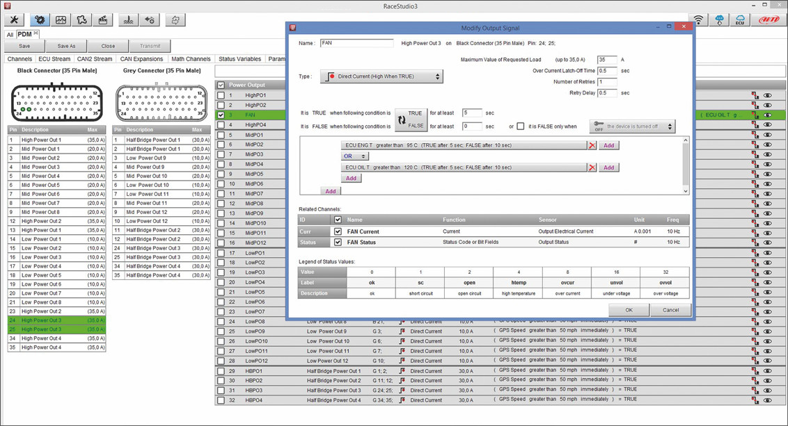
Each output provides status feedback for open circuit, short circuit, high temperature, over current, under voltage and over voltage. Inrush current, number of fault retries and the time between retries are all
definable. |
|
All the outputs may be configurable as PWM and allow soft start/stop.
For each output, a multicolor LED shows the status:
|
|
|
Enabled/disabled |
|
|
Activated or not |
|
|
Fault |
|
|
An elegant visual interface allows flexible and powerful configuration for every power output.
|
|
 |
|
|
|
|
|
|
Special Functions |
|
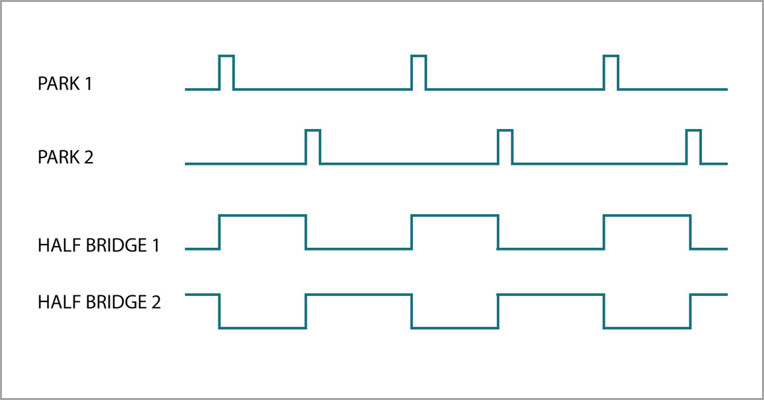
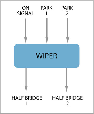
Some "black boxes" are available for simplifying the configuration.
For example, the Wiper may be managed by the LIN connection or using the Half Bridges.
In this case, you may take advantage by a virtual object like the following one: |
|
|
|
|
|
|
|
|
Inputs |
|
PDMs feature the following Inputs channels: |
|
|
PDM32 |
PDM08 |
|
|
|
Analog/Digital |
|
|
|
Only digital |
|
|
|
Speed |
|
| |
|
|
|
|
|
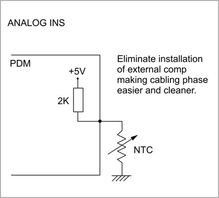
| Analog inputs |
|
Digital inputs |
|
 |
|
 |
|
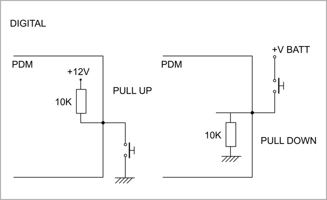
| If configured as Analog inputs, it is possible to activate an internal 2K Ohm resistor, for connecting most of the sensors directly. |
|
If configured as Digital Inputs, it is possible to activate a 10K Ohm Pull Up or a 10K Ohm Pull Down. |
|
|
|
|
|
|
|
| Dash |
|
Mirror Camera |
|
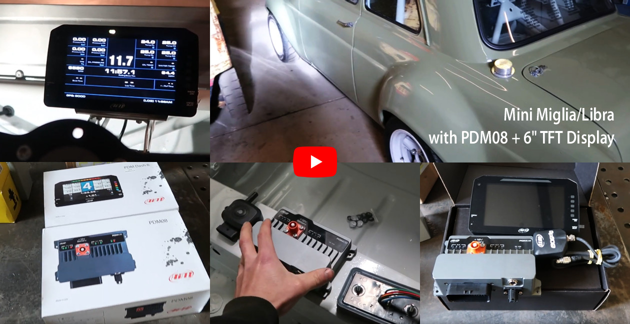
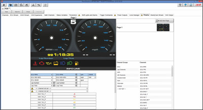
| Both the PDM08 and PDM32 support the 5", 6” and 10” TFT displays.
All fully configurable with RaceStudio 3. |
|
 |
|
|
PDM32 only features two analog camera inputs that allow you to swap your display into a mirror camera with the press of a button or through configurable event logic-reverse gear most commonly. |
|
| |
|
|
|
|
|
Data Management |
|
The PDMs receive, use and record data from: |
|
|
|
ECU: more than 1,000 protocols
available |
|
|
Digital/Analog inputs |
|
|
GPS: position and Lap Time |
|
|
Expansions |
|
|
|
Pushbuttons, from AiM K Keypads or any commercial CAN keypad, thanks to the simple configurability of the CAN protocols |
|
|
All the currents and status
of all the
power outputs |
|
|
Other user defined math channels |
|
|
|
|
|
|
|
|
|
GPS |
|
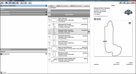
PDMs come with 4,000 tracks
in their database and automatically
select the one you are driving on,
in order to calculate Lap Time
when you pass the start/finish line. |
|
|
|
|
|
|
|
|
Data Logger |
|
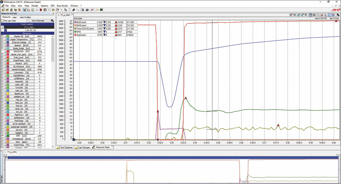
An internal datalogger is available, capable of recording all the analog inputs, digital inputs, ECU channels, GPS values, Currents, status of all the Power Outputs.
Here an example of what the recorded data may show, during engine cranking. |
|
|
In red, the ignition pushbutton |
|
|
In blue, the battery voltage drop |
|
|
In purple, the current absorbed by the solenoid |
|
|
In dark green, the current absorbed by the fuel pump |
|
|
In green, RPM Value |
|
|
 |
|
|
|
|
|
|
|
|
|
|
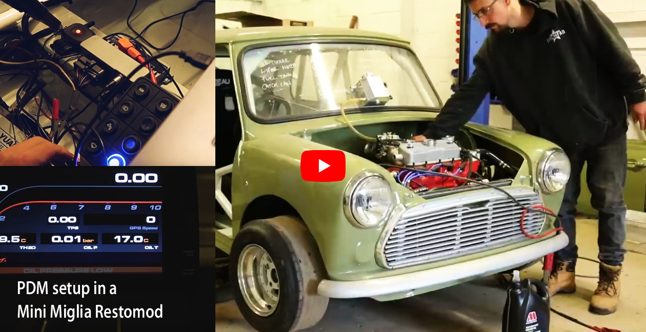
| FOLLOW THE ROGER CADDELL FREE ONLINE SEMINARS ABOUT PDM |
|
| The webinars co-hosts are AiM Hardware Chief Designer Fabrizio Rizzi and AiM Sports Chief of Technology Robbie Yeoman. |
|
|
|
|
|
|
|
| Please note that you can find ALL the seminars and much more on the AiM Sports YouTube page. |
|
|
|
|
|
|